Fluorescence imaging
By the end of this page you have inserted the objective, focused, taken a multi-channel image and a z-stack, and know how to read the fluorescence view and the image viewer.
This page is for the Arctis, whose fluorescence microscope sits under the grid. Support for offset fluorescence microscopes, the iFLM and the METEOR, is in development; on those systems the tab appears but this page does not yet describe them. On an instrument with no fluorescence microscope there is no Fluorescence tab, and you can skip to the AutoLamella section.
Before you start
- You are connected to an Arctis or the simulated Arctis, at the SEM orientation, with the feature of interest in coincidence.
- The sample is fluorescently labelled, or you are on the simulator, whose cells carry a nuclear dye, a cell-body dye and a second dye on a subset.
1. The Fluorescence tab
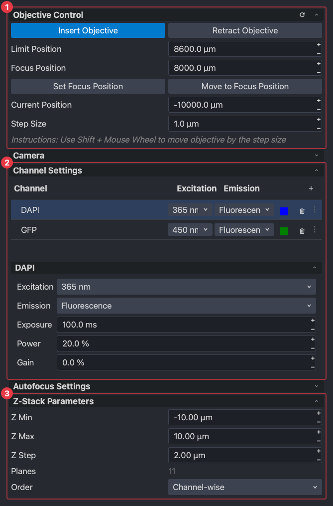
- (1) Objective control: insert and retract the objective, its current position, the focus position and a step size. The objective is retracted when you arrive.
- (2) Channel settings: the list of channels to image, and the selected channel’s excitation line, emission filter, exposure, light power and gain.
- (3) Z-stack parameters: the range and step for a stack, and the order the planes and channels are taken in.
Between them, collapsed, are the camera settings, autofocus settings and an image histogram. Below the panels are the buttons:
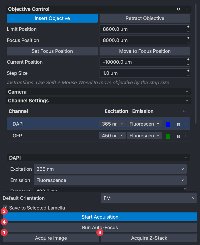
- (1) Acquire Image takes every channel in the list, one plane each: one file with all the channels in it.
- (2) Start Acquisition streams the selected channel live until stopped.
- (3) Acquire Z-Stack takes every channel at every plane of the stack.
- (4) Run Auto-Focus searches the objective around its position for the sharpest image on the autofocus channel.
2. Insert the objective and focus
Press Insert Objective. The objective can only come in with the stage at a tilt it can clear, so the button asks which tilt to insert at, moves the stage there if needed, and inserts. While it is inserted the instrument restricts the stage: z and tilt moves that could run the sample into the objective are refused, so retract it before tilting to the milling angle.
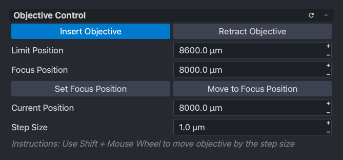
Move to Focus Position brings the objective to the position recorded as in focus for this instrument; Set Focus Position records the current one. To focus by eye, start a live acquisition, hold Shift and scroll over the fluorescence view: each notch moves the objective by the step size, in the direction you scroll, and the frames show the result. Run Auto-Focus does the same search for you.
3. Channels
A channel is one excitation line, one emission filter and an exposure. Add one with +, pick the line and filter from those the instrument has, and give it a name and a colour. The colour is only how the channel is drawn; it changes nothing about the light.
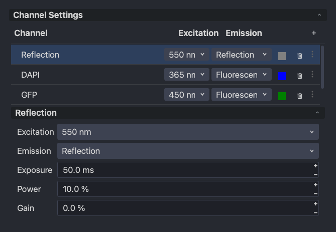
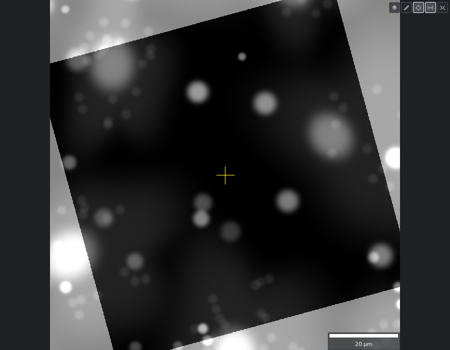
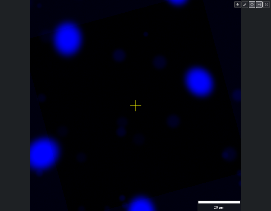
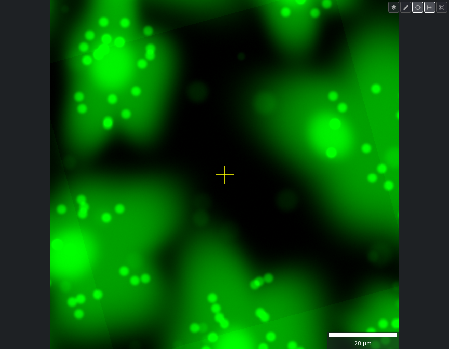
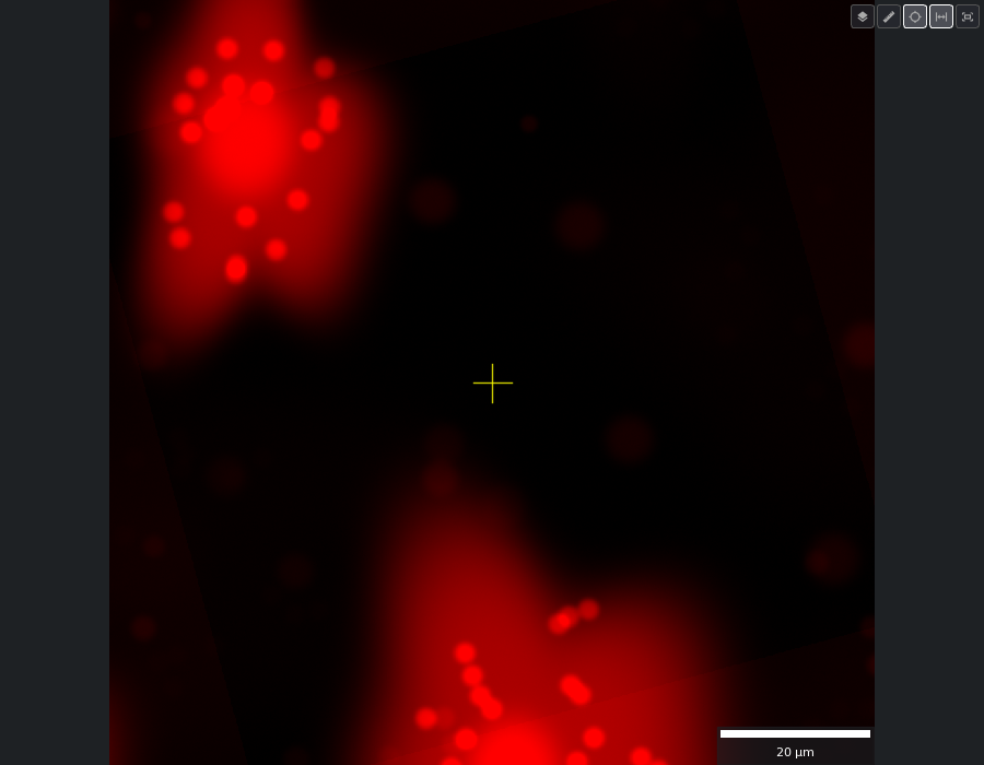
Reflection is the excitation light itself, collected without a filter: it shows the grid, bars bright and holes dark, and is the channel to navigate by. The others collect emitted light through the fluorescence filter and show only what the dye lights: on the simulator the 365 nm line lights nuclei, 450 nm the cell bodies and 550 nm a subset of cells, standing in for DAPI, GFP and mCherry.
Every channel in the list is taken by Acquire Image and Acquire Z-Stack. The highlighted one is the selected channel, which is what the live view streams.
4. The fluorescence view
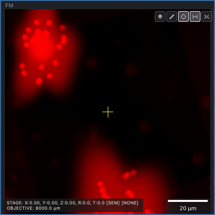
The fluorescence view on the Microscope tab is not the same kind of view as the SEM and FIB ones. It shows one frame: the last channel acquired or the live one, in that channel’s colour, and it is there for focusing, navigating and checking. Double-click in it to move the stage, as in the beam views; Shift and scroll moves the objective rather than the working distance.
To see all the channels of an image together, open it in the Fluorescence Image Viewer from the View menu: a separate window with the same canvas and a list of loaded images. It needs no experiment open. Every acquisition is written to disk as an OME-TIFF with all its channels and planes; Load Images… opens one, starting in the open experiment’s folder, and the details under the list say what is in it.
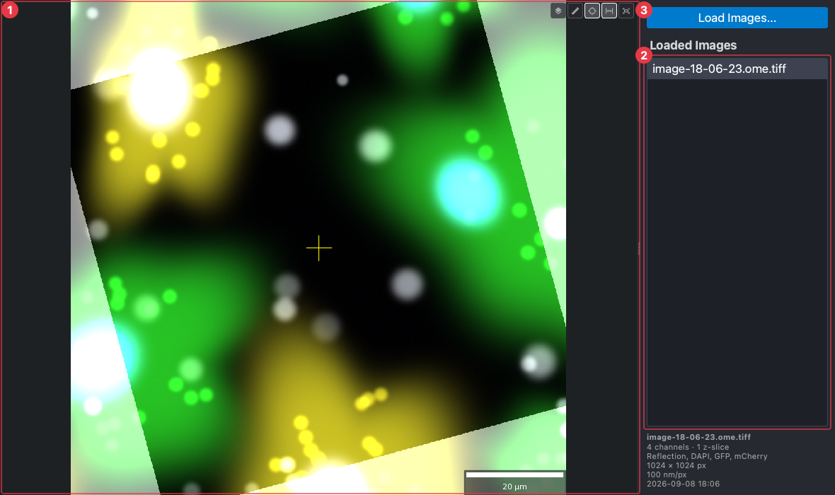
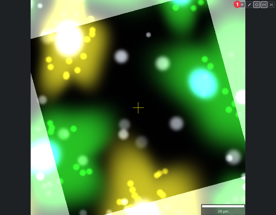
Here the four channels are composited, each in its own colour:
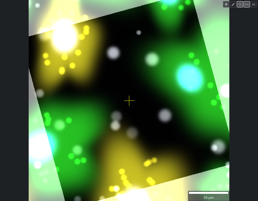
and each alone:
| Reflection | DAPI | GFP | mCherry |
|---|---|---|---|
 |  |  |  |
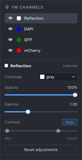
The canvas has the crosshair, scale bar, ruler and reset buttons of the beam views, and one of its own, the channels button:
It opens the channels panel. The eye beside each channel shows or hides it in the composite; click a channel to select it, and the controls below apply to that channel alone: its colormap, opacity, gamma, and the contrast range, with Auto to stretch it to the data. All of it is display only. Nothing here changes the image on disk; Reset adjustments puts it back.
5. Z-stacks
A z-stack images the sample at a series of objective positions, so a cell that is above or below the surface can be found and its depth read. Set the range either side of the current focus and the step; the panel says how many planes that is. Order is whether the whole stack is taken for one channel before the next (channel-wise, the default) or every channel is taken at each plane before moving on (z-level-wise).
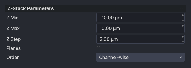
Press Acquire Z-Stack. With a stack loaded, the viewer’s canvas gains a row of slice controls and a max-projection button:
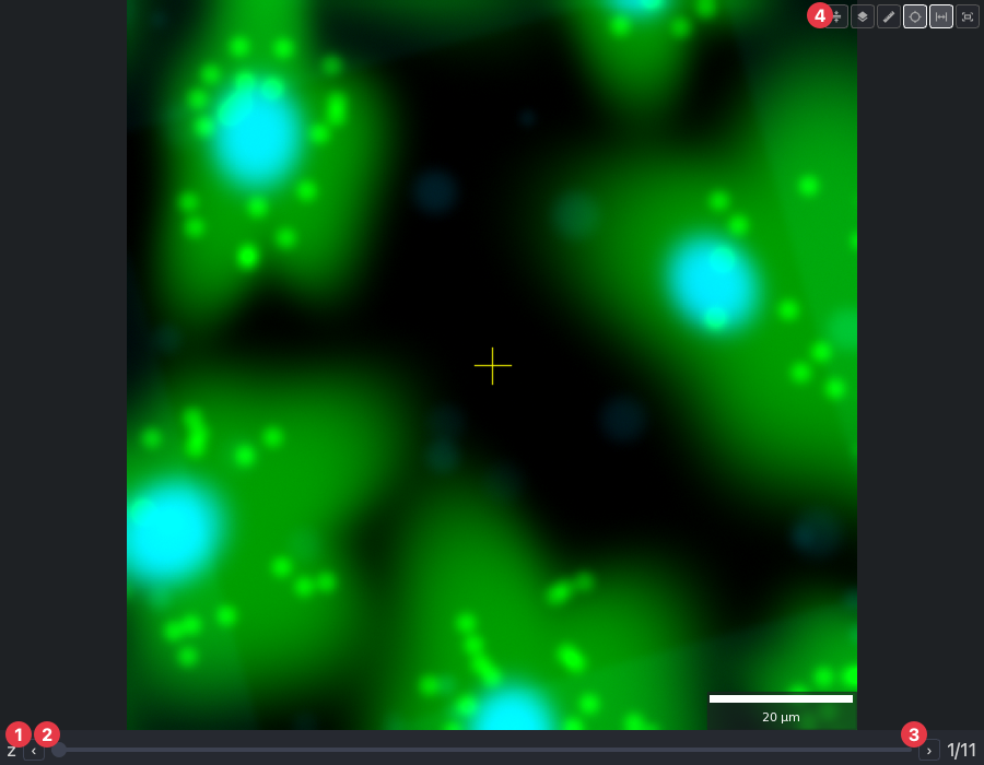
- (1) and (3) step one plane back and forward; (2) scrubs.
- (4) shows the maximum projection, every plane’s brightest value in one image, which is the quickest way to see every labelled cell at once.
Next
The AutoLamella workflow, where the fluorescence overview finds the cells to mill and the coincidence between the three beams is set up for you.