Sample holder
By the end of this page fibsemOS knows which holder is in the chamber, which grid is in each of its slots and where each slot sits on the stage, and you can move between grids by name.
Before you start
- You are connected and can image and move.
- The grids are loaded in the holder and you know which slot each is in.
1. The Sample tab
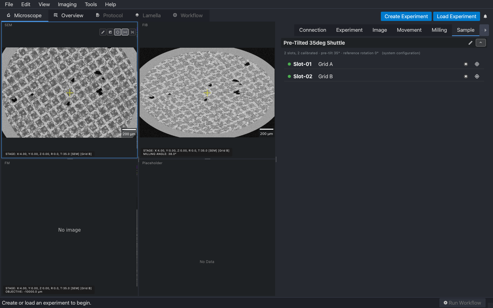
Open the Sample tab in the control panel. It is the instrument’s view of the grids: the holder, its slots, and what is in them.
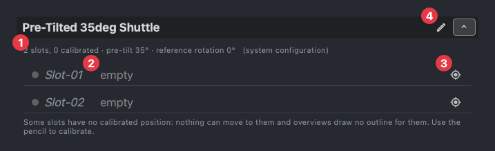
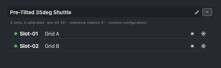
- (1) The holder’s facts: how many slots, how many are calibrated, and the pre-tilt and reference rotation it was calibrated against. The holder belongs to the instrument, not to a configuration.
- (2) One row per slot: a dot that is green once the slot has a calibrated position, the slot’s name, and the grid in it.
- (3) Move to this slot. Greyed out until the slot is calibrated.
- (4) The pencil: edit the holder’s name and slot count, and calibrate the slots.
The hint below the rows says what is missing. On a fresh install nothing is calibrated, so nothing can move to a slot yet.
2. Say which grid is where
Type a name into a slot’s row and press Enter. The name is the grid’s identity from here on: the views’ stage line shows it, positions and lamellae are recorded against it, and the Grids view of an experiment lists grids by it. Clear the name when the grid comes out.
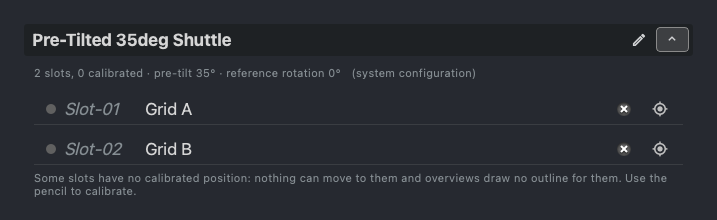
What is in the holder is remembered between sessions, so name grids when you load them and the next session starts knowing.
3. Calibrate the slots
A slot’s position is where its grid centre sits on the stage. It is measured once per holder, not per session, because the holder’s geometry does not change: only the grids in it do. Press the pencil to open the calibration.

Check the name and the slot count. Two for a standard shuttle.
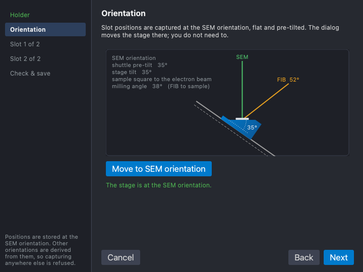
Positions are captured at the SEM orientation, flat and pre-tilted, and the other orientations are derived from them, so the dialog refuses to capture anywhere else. Press Move to SEM orientation and wait for the green line.
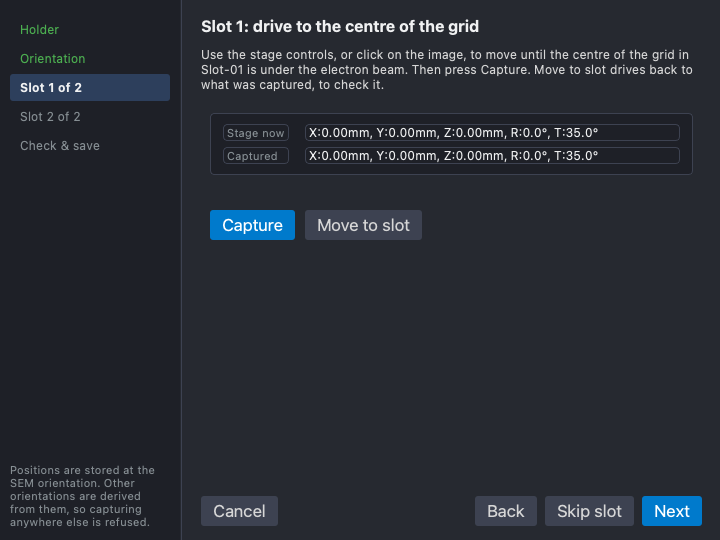
For each slot, drive the stage until the centre of that slot’s grid is under the electron beam. Use the Movement tab, or double-click in the SEM image at a low magnification where the whole grid is visible, then press Capture. The stage’s x, y and z are recorded; rotation and tilt come from the orientation. Move to slot drives back to what was captured, to check it.
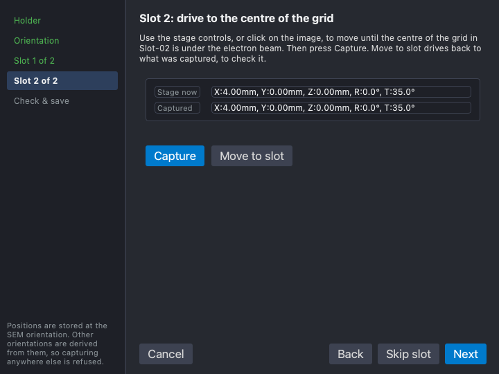
A slot with no grid in it can be skipped and calibrated later.
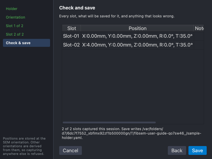
Save writes the holder file. Both slots now show a green dot, and the facts line says so.
4. Move between grids
Press a slot’s move button. The stage drives to that slot’s grid centre at the SEM orientation, the views are re-imaged, and the stage line names the grid you are now on. At a wide field of view you see the whole grid, its rim, and the holder around it.
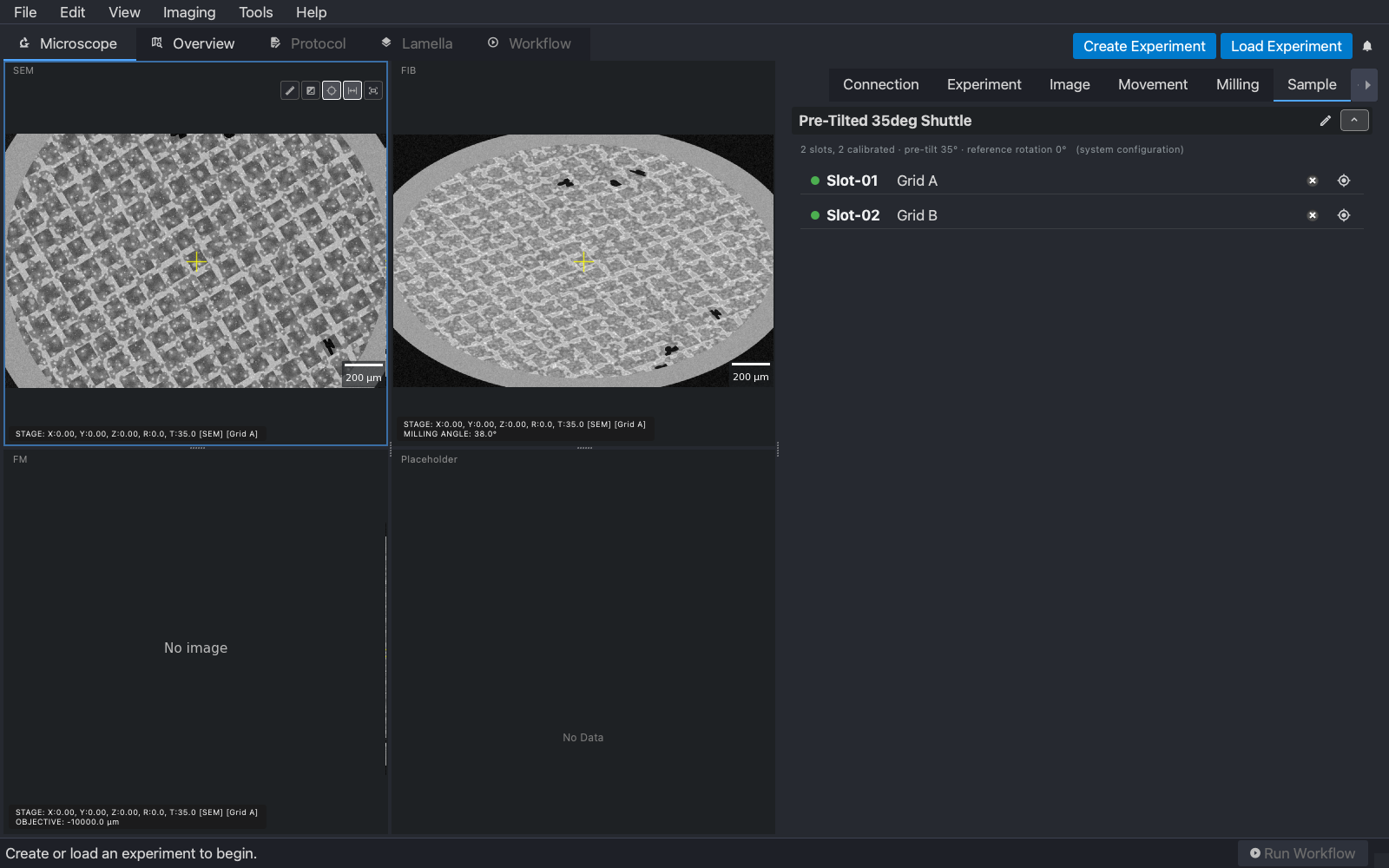
The AutoLamella overview uses the same positions to draw an outline for each grid, which is why the hint on an uncalibrated holder mentions overviews.
5. Where it lives
The holder is saved as sample-holder.yaml beside your configuration
files, and the grid names in sample-holder-occupancy.yaml next to it.
Both are shared by every configuration on that computer, because they
describe the instrument’s holder rather than a way of using it. If a
different holder is fitted, edit the name and slot count with the pencil and
calibrate it; the old positions are discarded because they no longer apply.
A position captured against a different pre-tilt or reference rotation is
also treated as uncalibrated, which is what the facts line’s “pre-tilt” and
“reference rotation” are telling you.
6. The Arctis: holder and loader (experimental)
On an Arctis the Sample tab has two panels. The holder is the compustage’s one working slot; below it is the Loader, the autoloader magazine with its twelve slots, which grids are in them, and buttons to scan the magazine and to bring a grid into the working slot or send it back.
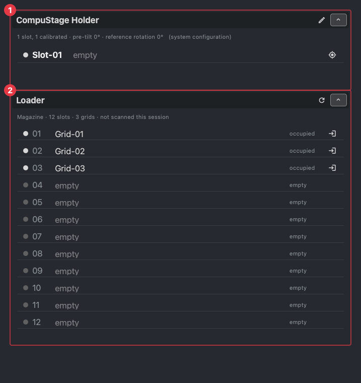
Loader support is experimental. The exchange itself runs on the instrument through AutoScript; on the simulator the magazine is listed but nothing moves. Name grids in the magazine as you would in a shuttle slot, and use the instrument’s own software for anything the panel does not offer.
Next
Fluorescence imaging on an Arctis, or straight on to the AutoLamella workflow.