Stage movement
By the end of this page you can put the stage in each of the three orientations and say what they are for, move around the grid by double-clicking in an image, and bring the two beams back into coincidence when they drift apart.
Before you start
- You are connected and have taken a first image of the grid.
- On a real instrument, know the stage’s limits and where the pole pieces and detectors are. fibsemOS moves the stage with the same commands the instrument’s own software uses and no others, but it does not know what is in the chamber.
1. The Movement tab
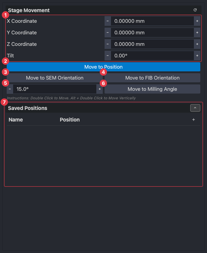
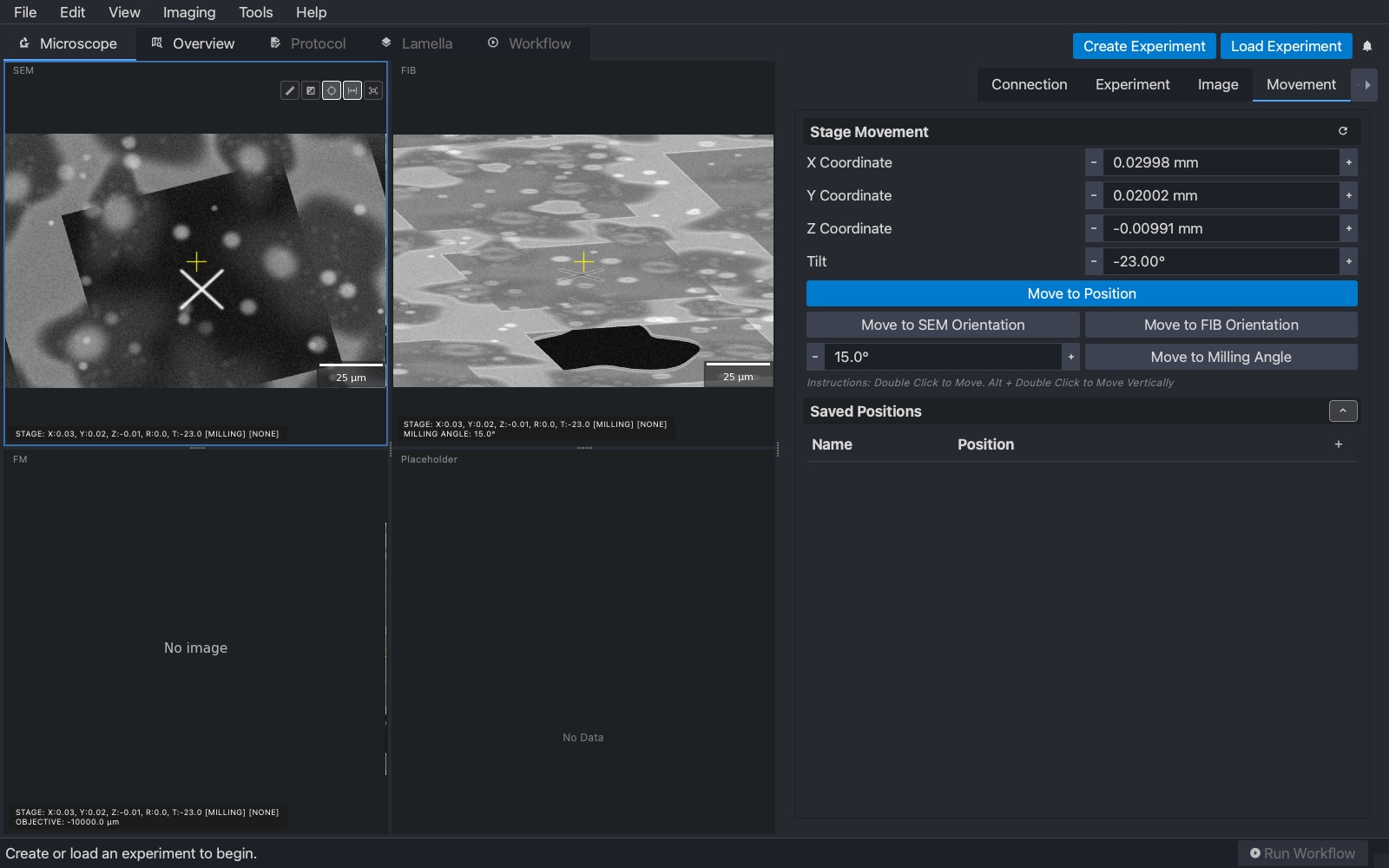
- (1) The stage position: x, y, z, rotation and tilt, as the instrument reports them. Type a value and press (2) Move to Position for an absolute move. The refresh button at the top right re-reads the stage.
- (3) Move to SEM Orientation and (4) Move to FIB Orientation: the two flat orientations, explained below.
- (5) The milling angle and (6) Move to Milling Angle: the third orientation, tilted for milling.
- (7) Saved positions: bookmarks for the stage. Press + to save where you are now, name it, and use the buttons on each row to go back to it, update it to the current position, or remove it. They are kept in a file beside the configuration, shared by every configuration on the computer.
Below the buttons the tab reminds you of the two mouse gestures this page is mostly about: double-click to move, Alt + double-click to move vertically.
2. The three orientations
A FIB-SEM has two beams at a fixed angle to each other, 52° on Thermo Fisher instruments, and a stage that rotates and tilts. Different tasks need the sample viewed from particular directions, and the stage geometry and the pre-tilt of the holder turn those into a few specific stage poses the instrument is used in. fibsemOS names three of them and moves to each with one button.
- SEM orientation, sometimes called the mapping position: the sample is flat, square to the electron beam. Used for overview acquisition and for picking positions.
- FIB orientation, sometimes called the trenching position: the sample is square to the ion beam. Used for trench milling on high-pressure-frozen samples, and to look at a lamella face-on.
- MILLING orientation: the sample is tilted so the ion beam meets it at a shallow angle, the milling angle. Used for milling lamellae.
What those poses are in stage coordinates is set by the two numbers from the stage step of Guided Setup: the reference rotation is the stage rotation of the SEM orientation, and the shuttle pre-tilt is its stage tilt. The other two orientations are derived from them. The diagrams below are drawn from the shipped configurations for the two kinds of stage; the app draws the same picture on that step of Guided Setup.
A pre-tilted shuttle (Aquilos, Hydra)
The shuttle holds the grid at a fixed 35° wedge, so the stage tilts by 35° to make the sample flat to the SEM. The FIB orientation is a half turn of the stage rotation from the SEM one, which flips the wedge the other way and lets the stage tilt to 17° (52° minus 35°) to face the ion beam.
| SEM | MILLING | FIB |
|---|---|---|
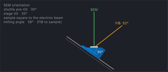 | 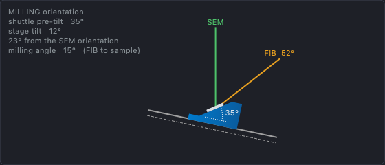 | 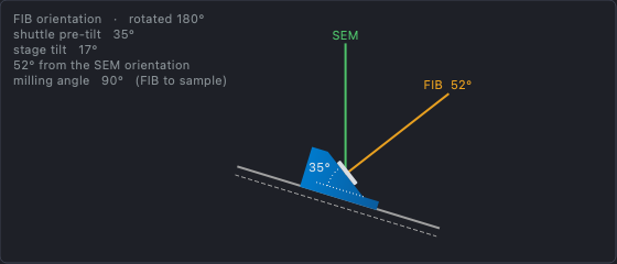 |
The rotation the SEM orientation uses is the reference rotation from Guided Setup. MILLING shares it; FIB is 180° from it.
A compustage (Arctis)
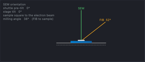
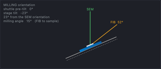
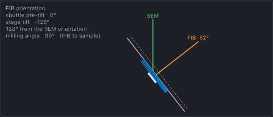
There is no wedge, so the sample is flat to the SEM at zero tilt, and no rotation is involved in any orientation. The compustage reaches the ion beam by tilting the other way and through: the FIB orientation is at −128° tilt (52° short of a half turn), so the ion beam meets the grid square-on from behind, and lamellae are milled from the back of the grid. The MILLING orientation is likewise on the negative side, at −23° for a 15° milling angle.
| SEM | MILLING | FIB |
|---|---|---|
 |  |  |
3. The milling angle
The milling angle is the angle between the ion beam and the sample surface. Lamellae are milled at a shallow one, typically 10° to 20°, so the beam grazes the surface and thins from both sides.
It is not a fixed pose. The stage tilt that gives a chosen milling angle depends on the column angle and the pre-tilt, and fibsemOS works it out from the number in the milling-angle box on the Movement tab: stage tilt equals milling angle plus column tilt plus pre-tilt minus 90°. The MILLING orientation is simply the pose for the milling angle currently set, and changing the number changes where Move to Milling Angle goes. The default is 15°; a protocol carries its own.
The FIB view always shows the milling angle for the tilt the stage is at right now, in the text at its bottom left. At the SEM orientation on an Arctis it reads 38°: the ion beam is 52° from vertical, so a flat sample meets it at 90° minus 52°.
4. Move by double-clicking
Double-click on any feature in the SEM or FIB view and the stage moves so that feature is under the beam centre, and both views are re-imaged. This is how you navigate a grid: overview image, double-click a square, image again, double-click a cell.
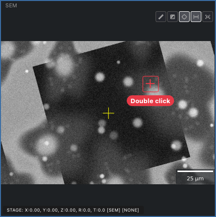
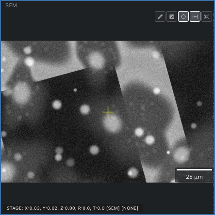
This is a stable move: it moves the stage along the sample surface, not along the stage’s own x and y. fibsemOS takes the distance you clicked in the image, in that view, and turns it into a stage move that keeps the sample at the same height under the beams, allowing for the shuttle pre-tilt, the current stage tilt, and the angle of the beam you clicked in. So a double-click in the FIB view, where the sample is foreshortened, moves the same distance across the surface as the same feature clicked in the SEM. If it did not, every move would also change the focus and the coincidence, and you would be correcting both after every step.
5. Coincidence and the vertical move
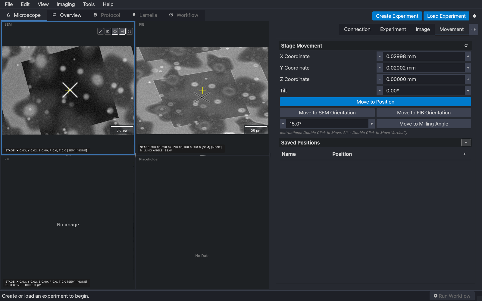
The two beams cross at one point in the chamber, the coincidence point. When the sample surface is at that height, a feature centred in the SEM view is also centred in the FIB view. When it is not, the SEM still shows the feature in the middle (looking straight down, height barely matters) but the FIB, looking from 52°, shows it displaced up or down. Milling then happens beside the feature you meant, so restoring coincidence is the first thing done at every new position.
The simulator boots with a 10 µm height error and, for this example, a cross marked at the grid centre. Centred in the SEM, the cross sits below centre in the FIB:
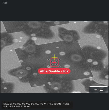
Hold Alt and double-click the cross in the FIB view.
This is a vertical move: the stage moves straight up or down in the chamber by the amount that puts the clicked feature under the ion beam’s centre. A vertical move is invisible to the electron beam, which is why the SEM image does not change, and the cross is now centred in both views.
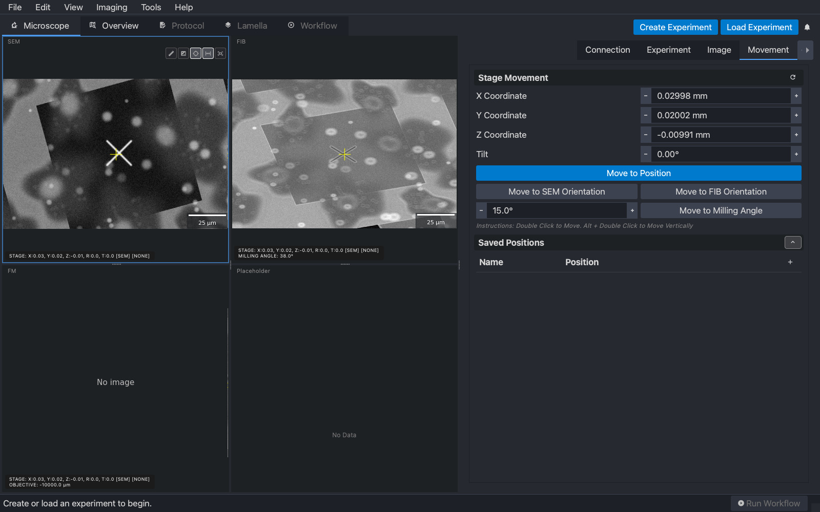
The stage z in the Movement tab has changed by the height error and nothing else has.
It works from either view. If the feature is centred in the FIB and off in the SEM, Alt + double-click it in the SEM instead; fibsemOS moves the stage along the ion beam’s axis by the amount that centres it there.
The AutoLamella workflow makes the same correction for you at each lamella, from a measurement rather than a click.
6. Eucentricity
Coincidence is about height: the sample surface at the point where the two beams cross. Eucentricity is about the tilt axis: the surface at the height the stage tilts about, so that tilting the stage turns the sample in place and a feature under the beam stays under it. The two are different things. The beams are aligned by the manufacturer to cross at the tilt axis, but the height of that axis is a property of the mechanics, and on most stages it is not exactly where the beams cross. So you can be perfectly coincident, with a feature centred in both views, and still watch it slide away when you tilt.
This is that case on the simulator. The cross is in coincidence, and the surface sits 30 µm above the tilt axis. Tilting to the MILLING orientation swings it along the surface, down in the SEM view and, foreshortened, in the FIB view, and changes its height, so the coincidence just set is lost as well:
fibsemOS does not set the eucentric height. Finding it means tilting, measuring the shift and adjusting z several times over, and it is not needed for what the workflow does. After a tilt the workflow takes an image, re-centres the feature with a stable move and restores coincidence there, which is why each lamella keeps a milling position recorded at its own tilt. By hand, do the same: tilt, then double-click the feature to bring it back.
Next
Milling: draw a pattern on the FIB view and mill it.