Spot burns and correlation
By the end of this page a lamella’s milling position sits on a fluorescent feature: the ion beam has burnt fiducial marks next to the target, a fluorescence z-stack has been acquired over them, and the two have been correlated so the point of interest in the fluorescence image is placed on the FIB image.
The burn and the correlation work on any instrument. The one step that depends on the microscope is acquiring the stack: on an Arctis the in-chamber fluorescence microscope takes it as a workflow task; on a system with a METEOR the stack is acquired with the METEOR’s own software and loaded into the correlation dialog from disk. Support for driving a METEOR from fibsemOS is planned.
Before you start
- A lamella marked on a cell.
- On an Arctis, the lamella’s fluorescence pose with an objective position. A lamella added while the objective is inserted records it; otherwise Use current objective position on the Experiment tab sets it. The Fluorescence imaging page covers the channel and z-stack settings the acquisition task takes.
- On an Arctis, Sync Fluorescence Pose turned on in the Setup Lamella Position task. Setup centres the site and re-records the milling position; with this on, the fluorescence pose follows it, so the stack is taken where the marks are rather than where the lamella was first marked. It is off by default.
1. Why correlate
The fluorescence overview says which cell to mill. It does not say where, in the FIB image, the fluorescent structure inside that cell sits, or how deep. Correlation answers both: marks that both microscopes can see are burnt into the surface, their positions are picked in the FIB image and in the fluorescence stack, and a transform between the two is fitted. A point picked in the fluorescence stack then maps to a point in the FIB image, which becomes the position the lamella is milled at.
2. The two tasks
Two tasks are added to the protocol (Tasks covers adding a task): the burn after the setup task, and the acquisition after Mill Fiducial. Burn the marks and mill the fiducial before acquiring the stack, so that both are in it: the stack is then a record of the site as it will be milled, and the fiducial is one more feature the two images share. On a system without an in-chamber fluorescence microscope, only the first task applies.
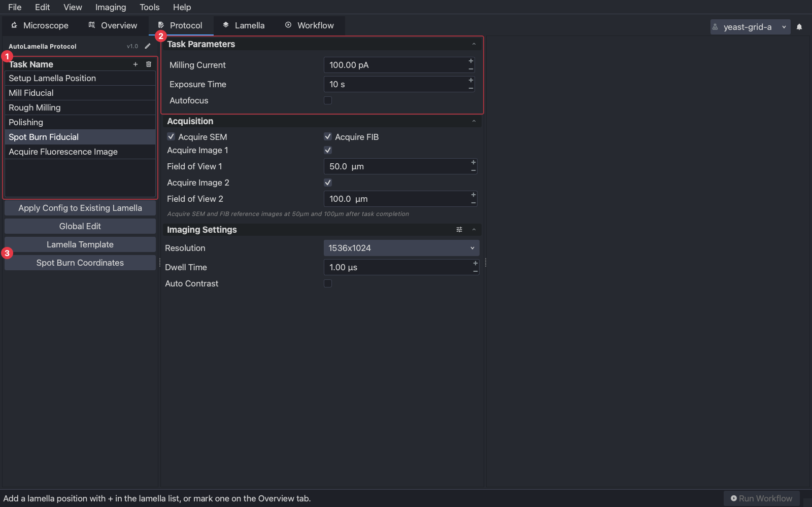
Spot Burn Fiducial parks the ion beam on each of a set of points for a few seconds at a low current, leaving a small mark in the surface at each.
- (1) The task in the protocol’s task list.
- (2) Its settings: the milling current, the exposure time per point, and whether to autofocus the ion beam first. Use at least 100 pA, the default; below that the marks are too faint to find in the fluorescence image. The reference images below them are taken after the burn, at the two fields of view given.
- (3) Spot Burn Coordinates edits the points themselves, in normalised coordinates of the reference image. Four to six points spread around the target, not in a line and not symmetric, give the fit something to hold on to. Supervised, the points can also be placed on the image when the task asks.
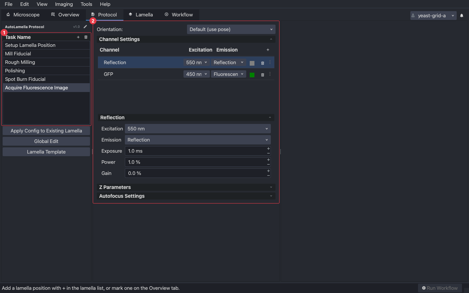
Acquire Fluorescence Image (its settings at (2)), Arctis only, moves to the lamella’s fluorescence pose, inserts the objective to the recorded position, and acquires a z-stack with the configured channels. Include the reflection channel, which is where the burn marks show, together with the channel the target fluoresces in. The z-range should span the depth of the target; the step sets how finely its depth can be read. The task retracts the objective afterwards unless told not to.
With a METEOR, acquire the same kind of stack in its software after the burn, with a reflection channel and the target’s channel, and save it as an OME-TIFF. Copy it into the lamella’s folder to have it listed on the Lamella tab, or load it from anywhere with the … button beside the FM image in the correlation dialog.
3. Running them
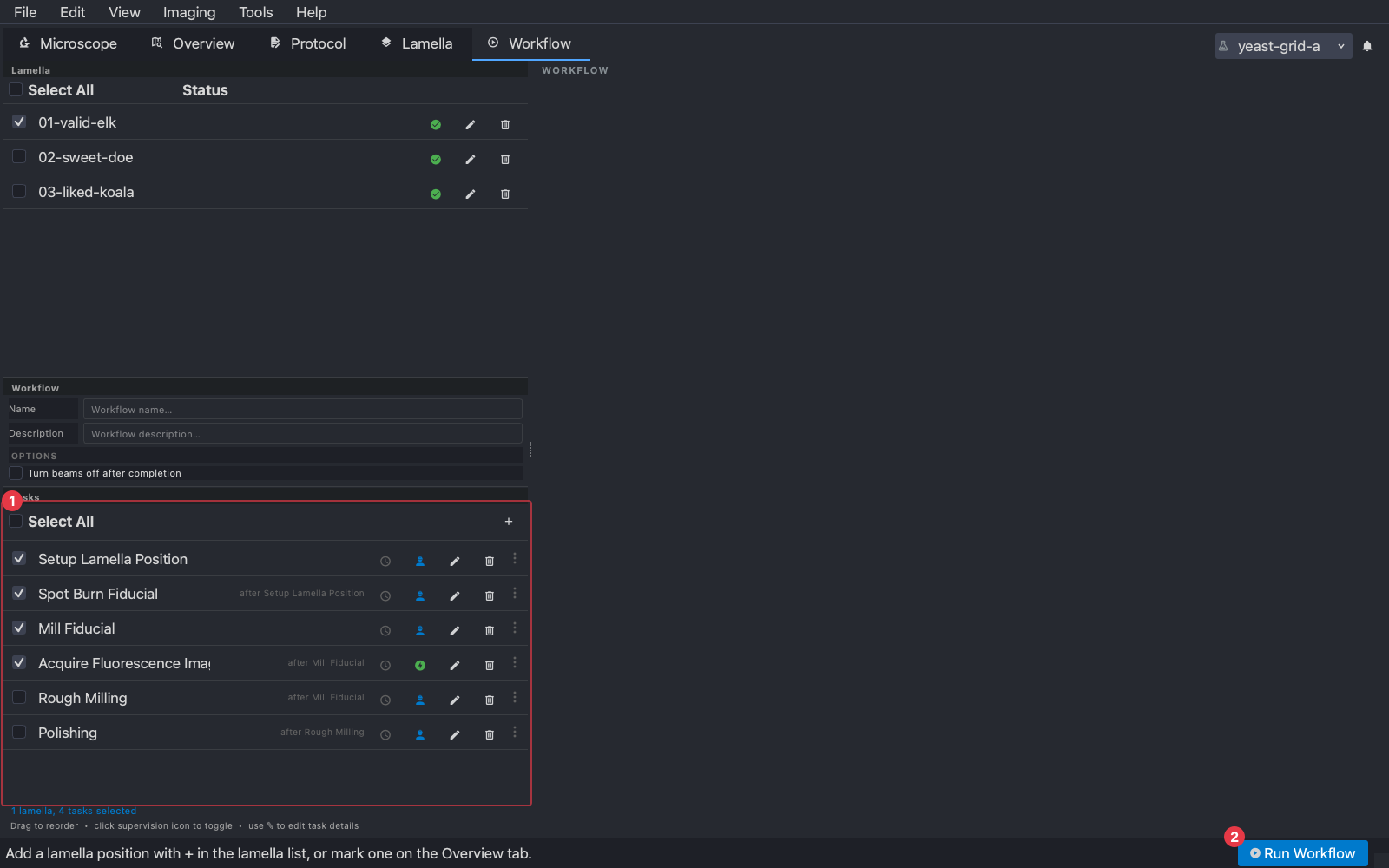
Select the lamella and the setup, burn and fiducial tasks, and on an Arctis the acquisition task, on the Workflow tab and press Run Workflow (Workflows).
Supervised, the burn task stops before burning:
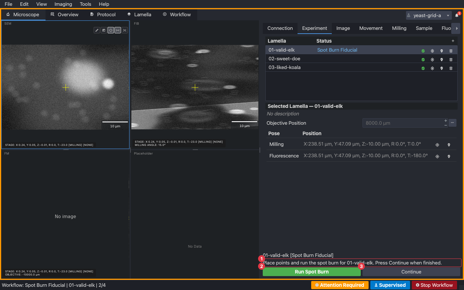
- (1) The question.
- (2) Run Spot Burn burns the points as placed. The question returns when the burn has finished, so the marks can be checked and more burnt.
- (3) Continue accepts the marks and moves on.
The points are shown on the FIB view, and the Spot Burn tab holds them:
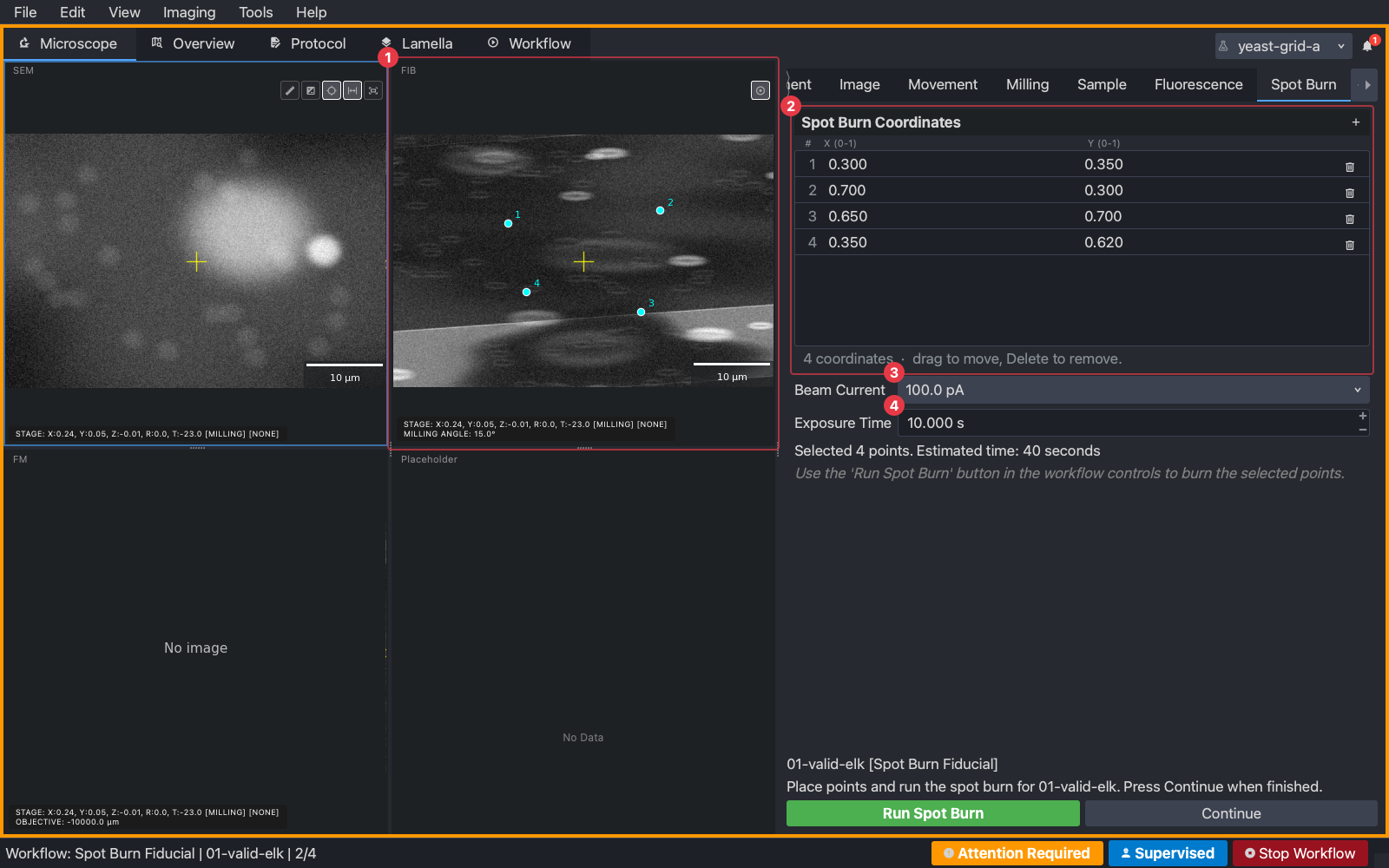
- (1) The points on the FIB view. Right-click to add one; drag to move.
- (2) The point list, in normalised coordinates.
- (3) The milling current and (4) the exposure per point.
After the burn the task acquires reference images at both fields of view. Mill Fiducial then mills the fiducial and asks in the same way, and the acquisition task takes the fluorescence stack. Everything lands in the lamella’s folder.
By hand
A burn does not need a workflow. The Spot Burn tab on the Microscope tab is the same panel outside a task: right-click the FIB view to place points on the current image, set the current and exposure, and press Run Spot Burn. The marks are burnt where the points sit on the image on screen, so image the site at the field you want first.
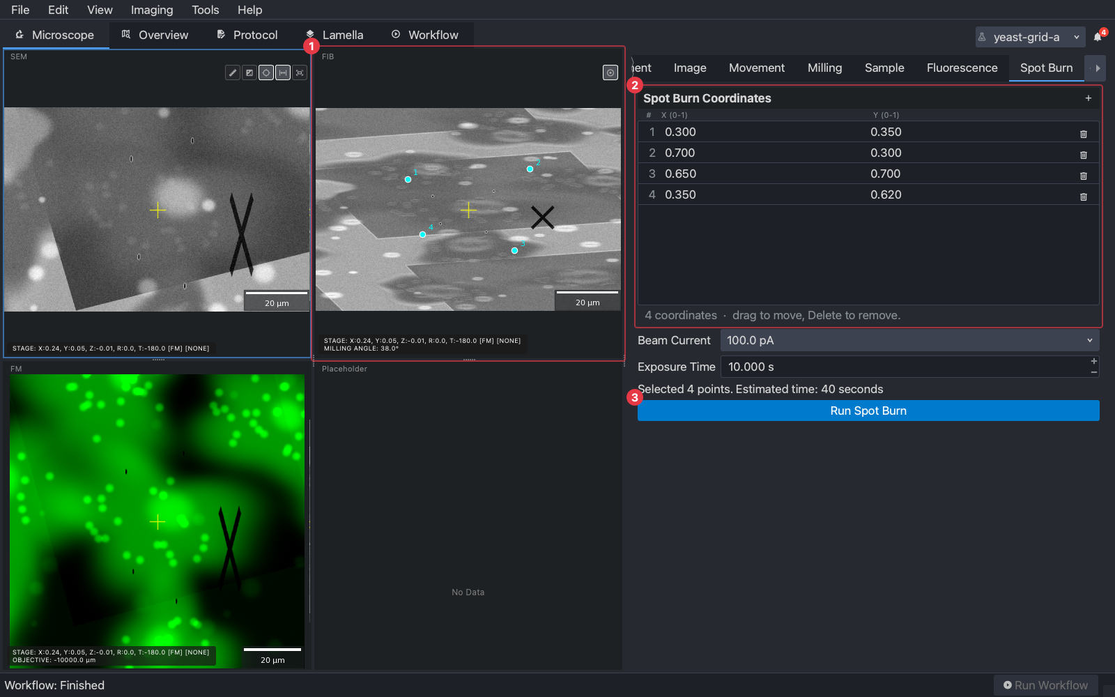
4. The Lamella tab
On the Lamella tab, with the burn task selected, the FIB view shows the latest reference image, here Mill Fiducial’s, with the marks and the fiducial in it:
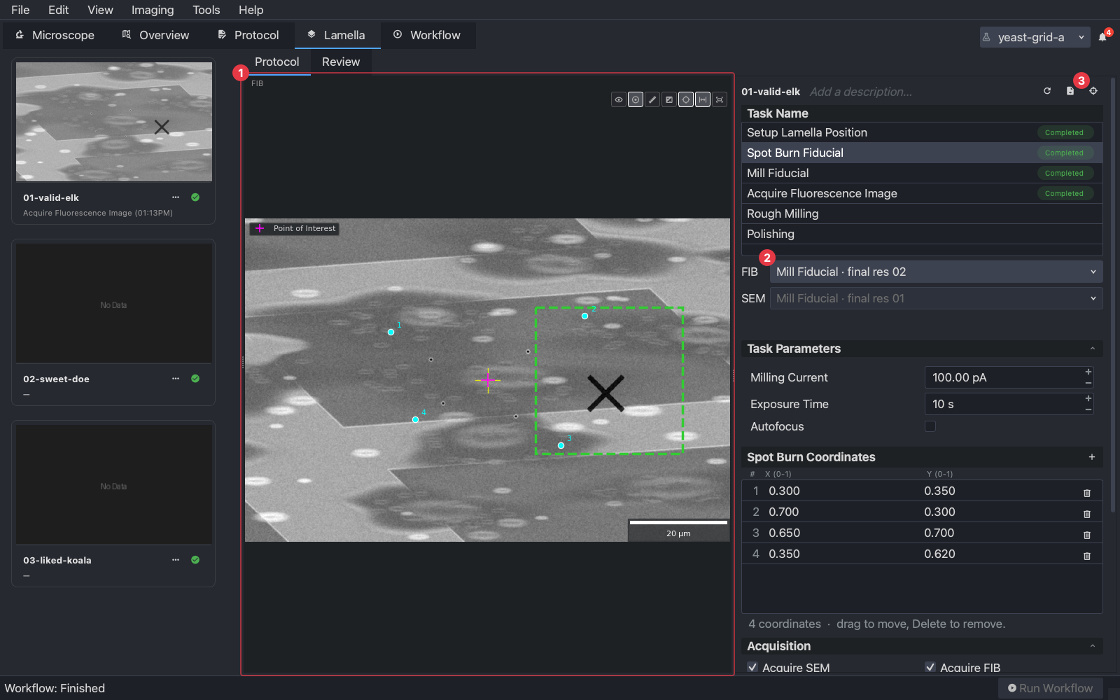
- (1) The FIB reference image with the burn marks and the fiducial. The numbered points are the coordinates the burn task was given, drawn by their normalised positions; on an image at another field than the burn’s they do not sit on the marks.
- (2) Which FIB image the correlation uses. Choose the one that matches the stack: the reference taken after Mill Fiducial, so the marks and the fiducial are in both images, at the smaller of its fields. The final references are numbered largest field first, so with two fields that is the second one.
- (3) The correlation button, a target icon, opens the correlation dialog.
The Spot Burn Coordinates panel under the task’s parameters holds this lamella’s own points. Editing them here changes where the next burn on this lamella lands, without touching the protocol or the other lamellae.
With the acquisition task selected, the view shows the stack instead, and the FM selector (2) says which stack is used:
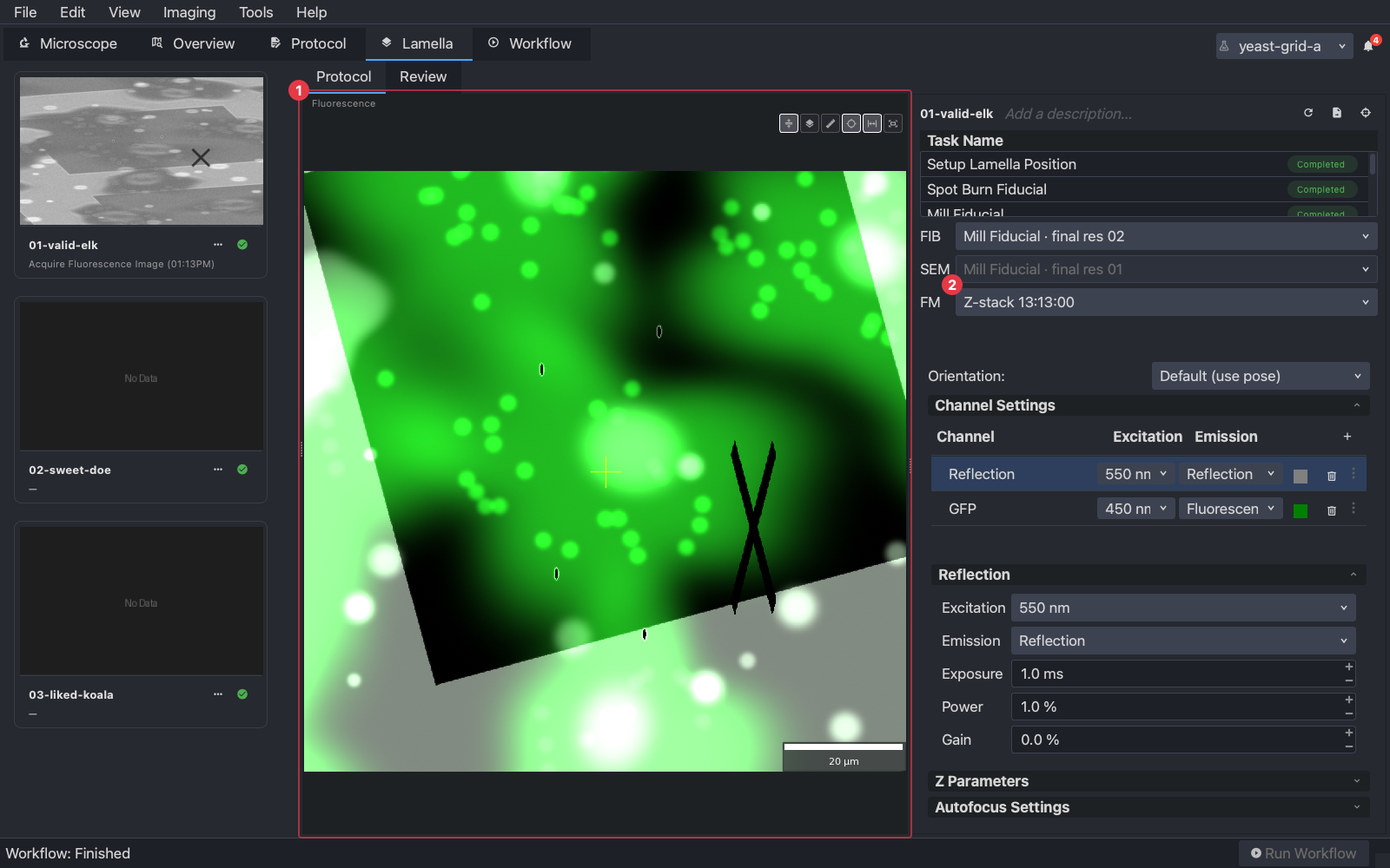
5. Correlating
The dialog opens on its Images tab with the FIB image and the fluorescence stack loaded:
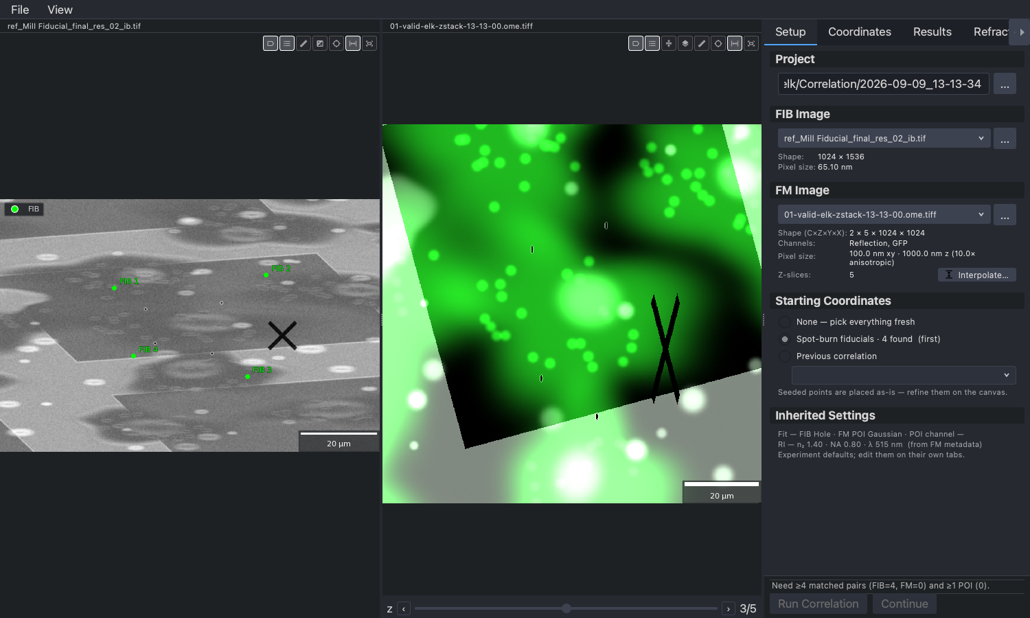
The FIB-side fiducials are already there: they are the points the burn task was given, in the order it burnt them, placed by their normalised coordinates. They are a starting point, not the answer: drag each onto its mark in the image. They will be off for two reasons. The points were placed on the burn task’s own image, and an image at another field puts them at another scale; and the burn runs at a different current from the imaging, and the beam shifts a little with the current, so the marks land near the points rather than on them. A fiducial left off its mark moves the result by that much. On the Coordinates tab, the fluorescence side is picked by hand. Select the reflection channel as the fiducial channel, scrub to the plane where the marks are sharpest, and right-click each mark in the same order as the FIB list. Then select the channel the target fluoresces in, find the plane where it is sharpest, and right-click it to add the point of interest.
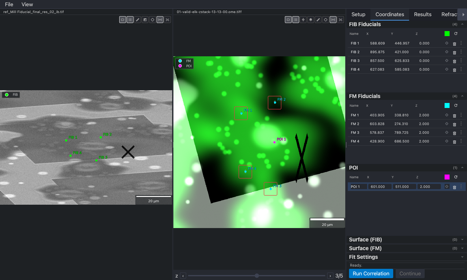
The boxes mark the burn marks in the fluorescence image: small dark points with a bright rim in the reflection channel, here composited with the target’s channel in green.
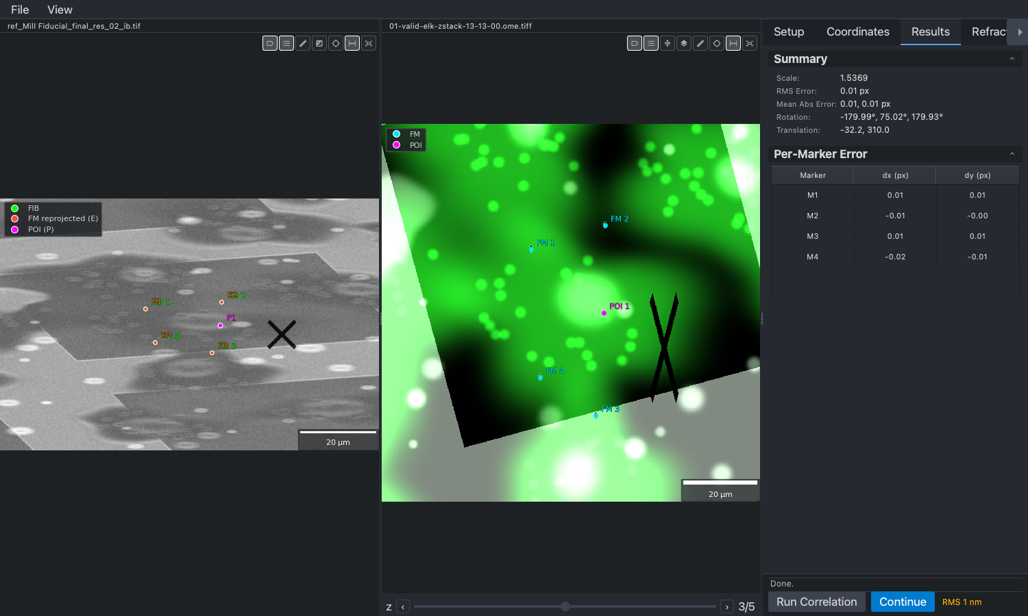
Run Correlation fits the transform from the pairs and projects the point of interest into the FIB image, where it is drawn over the marks. The Results tab reports the fit: the RMS error, the scale, and each fiducial’s error in pixels. An error of a few pixels is normal; one fiducial far off the others is usually a mark paired with the wrong point.
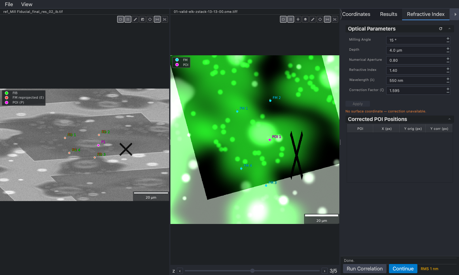
Refractive index. The sample surface in the fluorescence stack appears deeper than it is, because the light travels through ice with a refractive index above one. The Refractive Index tab corrects for it: add a surface point, on the FIB image at the sample surface or in the stack at the plane of the surface, and Apply scales the target’s depth about that surface by the factor shown. The factor comes from the optical parameters in the tab: the milling angle, the target’s depth, the objective’s numerical aperture, the refractive index of the ice and the wavelength, filled from the stack’s metadata where it has them. The correction is small for a target near the surface and grows with depth; apply it when the target is more than a micron or two down.
Continue asks for confirmation, then accepts the projected point as the lamella’s point of interest and closes the dialog. The milling patterns move with it:
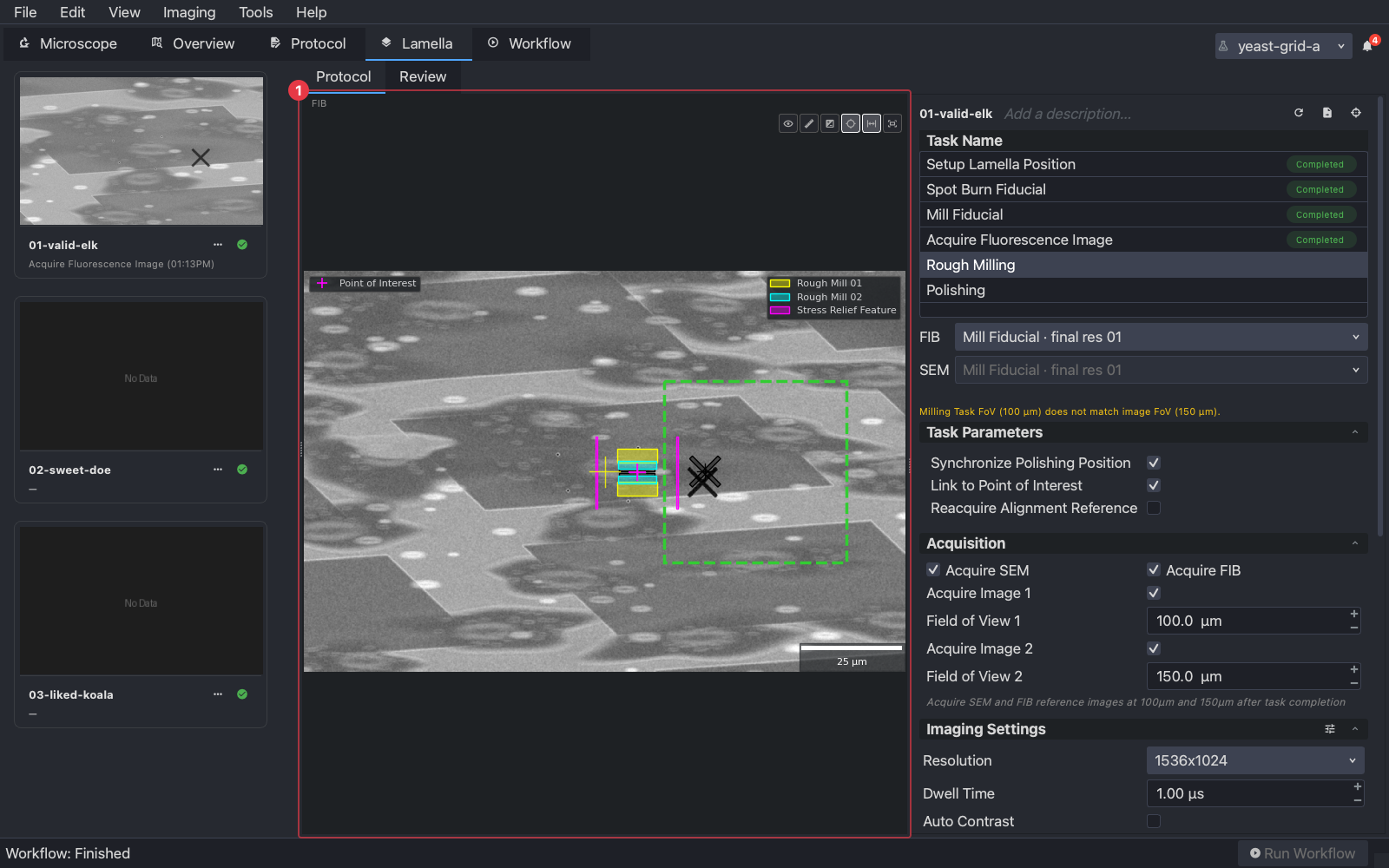
Check the FIB view before milling: the patterns should sit over the target cell, and the marks should be clear of them. Every correlation is saved in the lamella’s folder, so a later one can start from a previous one’s points.
6. A workflow with correlation in it
Setup Lamella Position, Spot Burn Fiducial and Mill Fiducial, then the fluorescence stack (the Acquire Fluorescence Image task on an Arctis; the METEOR’s software otherwise), then the correlation by hand on the Lamella tab for each lamella, then Rough Milling and Polishing as on the Tasks page. Supervise the burn the first time, to see where the points land; the acquisition needs no supervision.
Correlating more than once
For a target that is hard to see through the material above it, correlate in rounds. After the first correlation, a pre-milling step clears the material around the site at a high current, leaving the target and a margin. Acquire another stack, correlate again with the target now closer to the surface and clearer, then run the rough milling on the refined point. The sequence is: burn and fiducial, stack, correlate, pre-mill, stack, correlate, rough mill.
Pre-milling is a Rough Milling task with wide, high-current patterns placed to leave a generous margin around the point of interest. Use the Rough Milling task type for it, not Trench Milling, which is the waffle method for high-pressure-frozen samples (Tasks). A second Acquire Fluorescence Image task after it, and the same correlation on the Lamella tab, complete the round.
Next
Your first lamella for the milling half, or Workflows to run the milling on every correlated lamella at once.