Milling
By the end of this page you have set up a milling task with one stage, placed its pattern on the FIB view, milled it on the simulator and seen the trench appear in both views.
Before you start
- You are connected, have imaged the grid, and are at the MILLING orientation with the feature to mill in coincidence. Everything on this page happens in the FIB view, so take a fresh FIB image first.
- On the simulator, milled patterns are cut into the synthetic grid and show up in every later image, so you can try anything here without cost.
1. The Milling tab
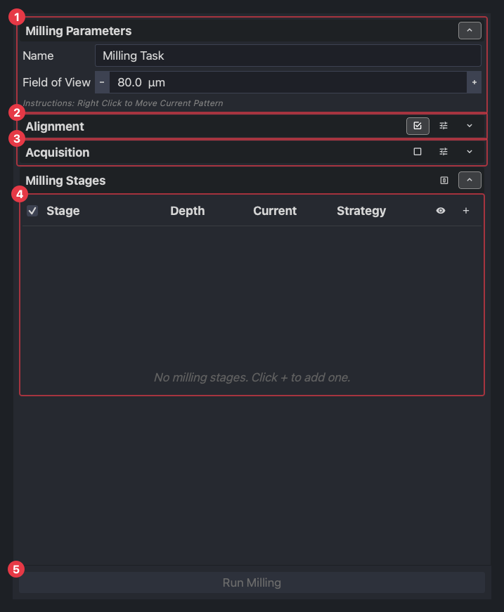
The tab holds one milling task: everything needed to mill one thing at one place. It has four parts, top to bottom.
- (1) Milling parameters: a name for the task and the field of view the FIB is set to while milling. Patterns are placed at this field of view, so choose it before placing them; 150 µm suits a lamella, a trench wants less.
- (2) Alignment: drift correction. Before each stage, fibsemOS takes a FIB image at that stage’s current and aligns it to the reference image, so a pattern lands where you placed it even though the beam moved when the current changed. On by default; the dashed box on the FIB view is the area it aligns on. Leave it on.
- (3) Acquisition: whether to take SEM and FIB images between the stages and a final image at the end, and with what settings. Off by default here; the workflow turns it on so every lamella keeps a record.
- (4) Milling stages: the list of what to mill, in order. This is where the work is.
- (5) Run Milling runs every ticked stage in order.
2. Milling stages
A stage is one pattern milled with one set of beam settings. A task can have several: a lamella is roughed at a high current, then thinned at a lower one, then polished at a lower one still, and each of those is a stage in the same task. Press + to add one.
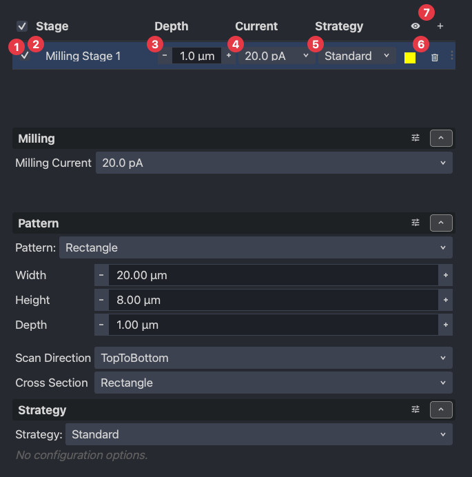
The row has the controls you change most:
- (1) ticked stages run; untick one to skip it without deleting it.
- (2) the name.
- (3) the depth to mill to.
- (4) the milling current.
- (5) the strategy (below).
- (6) remove the stage. Drag rows to reorder them.
- (7) adds a stage; the eye beside it hides the patterns on the view so you can see the sample underneath.
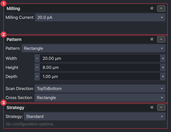
Select a row and the editor below it opens with three panels.
Settings
(1) Milling is the ion beam while this stage runs, with the milling current in front and the rest behind the slider icon: voltage, spot size, dwell time, and on Thermo Fisher instruments the application file, on Tescan the preset. The current is the one that matters day to day: higher removes material faster and coarser, lower slower and finer. Use the instrument’s own current list; the row shows only currents the beam has.
Pattern
(2) Pattern is the shape. The list starts with the basic shapes (rectangle, line, circle) and goes on to the shapes lamella preparation is built from: trench, horseshoe, undercut, fiducial, microexpansion and the rest. Each has its own fields; for a rectangle they are width, height, depth, scan direction and cross-section.
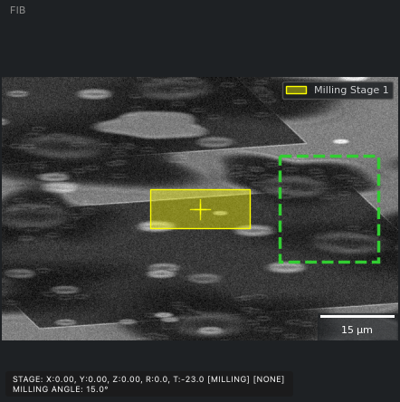
Patterns are placed relative to the FIB image: a new one appears at the beam centre, drawn in the stage’s colour, and moves when you move it, not when the stage moves. The green dashed box is not a pattern: it is the alignment area, the part of the image the drift correction compares between images, and it is only drawn while Alignment is on.
A few of the shapes, each at its shipped size:
| Rectangle | Trench | Fiducial | Micro-expansion |
|---|---|---|---|
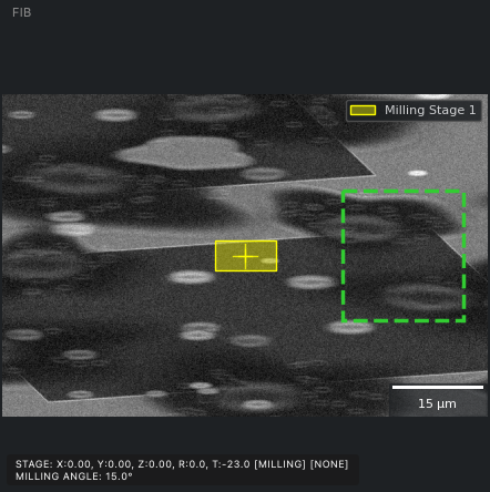 | 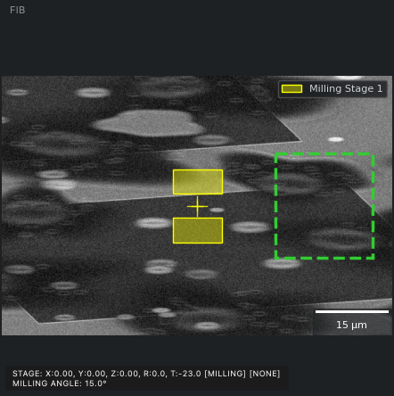 | 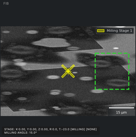 | 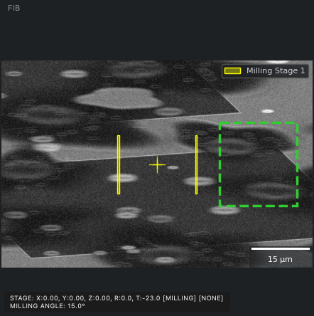 |
A trench is two rectangles with the lamella left between them; a fiducial is a cross the alignment can lock on to; micro-expansion cuts are the two lines beside a lamella that relieve stress in the film so it does not bend while thinning. Each of these is one stage’s pattern; a real lamella task combines several, and the shipped protocols already do.
To put a pattern somewhere else, right-click there on the FIB view and choose Move All Patterns Here, or the entry naming the selected stage to move only that one.
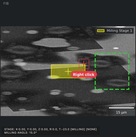
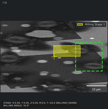
The instruction line under the milling parameters says the same thing. Every pattern must sit inside the FIB image; a move that would put one outside is refused with a message.
Strategy
(3) Strategy is how the pattern is milled. Use Standard. Others are coming and the plugin system can add more, but Standard is what the shipped protocols use.
More than one stage
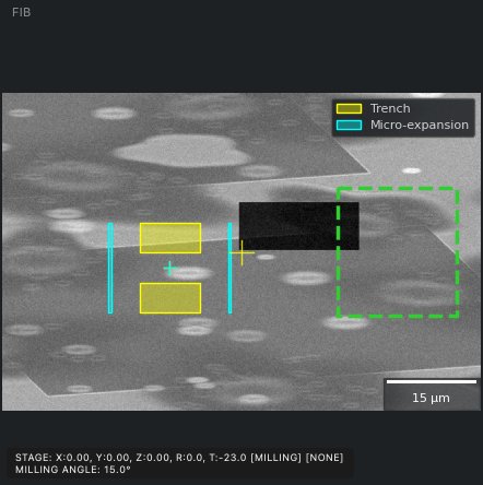
Add a second stage and the task mills them in list order, each with its own pattern and current, and the view shows every stage’s pattern in its own colour. Here the first stage is a trench and the second the micro-expansion cuts beside it.
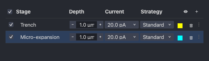
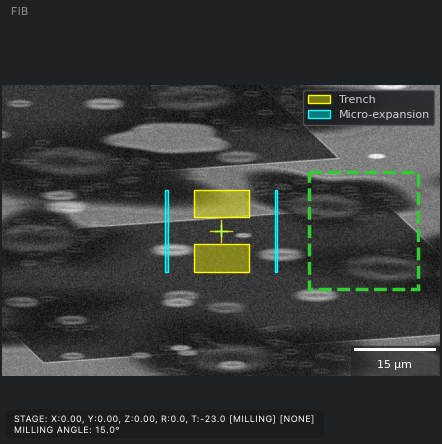
This is the shape of every lamella task in the shipped protocols: a handful of stages at decreasing currents, sharing one placement.
3. Run it
Press Run Milling. The task runs stage by stage: alignment first, if it is on, then the pattern. Two progress bars show which stage is running and how far it is, the status line says the same, and the button becomes Pause Milling and Stop Milling.
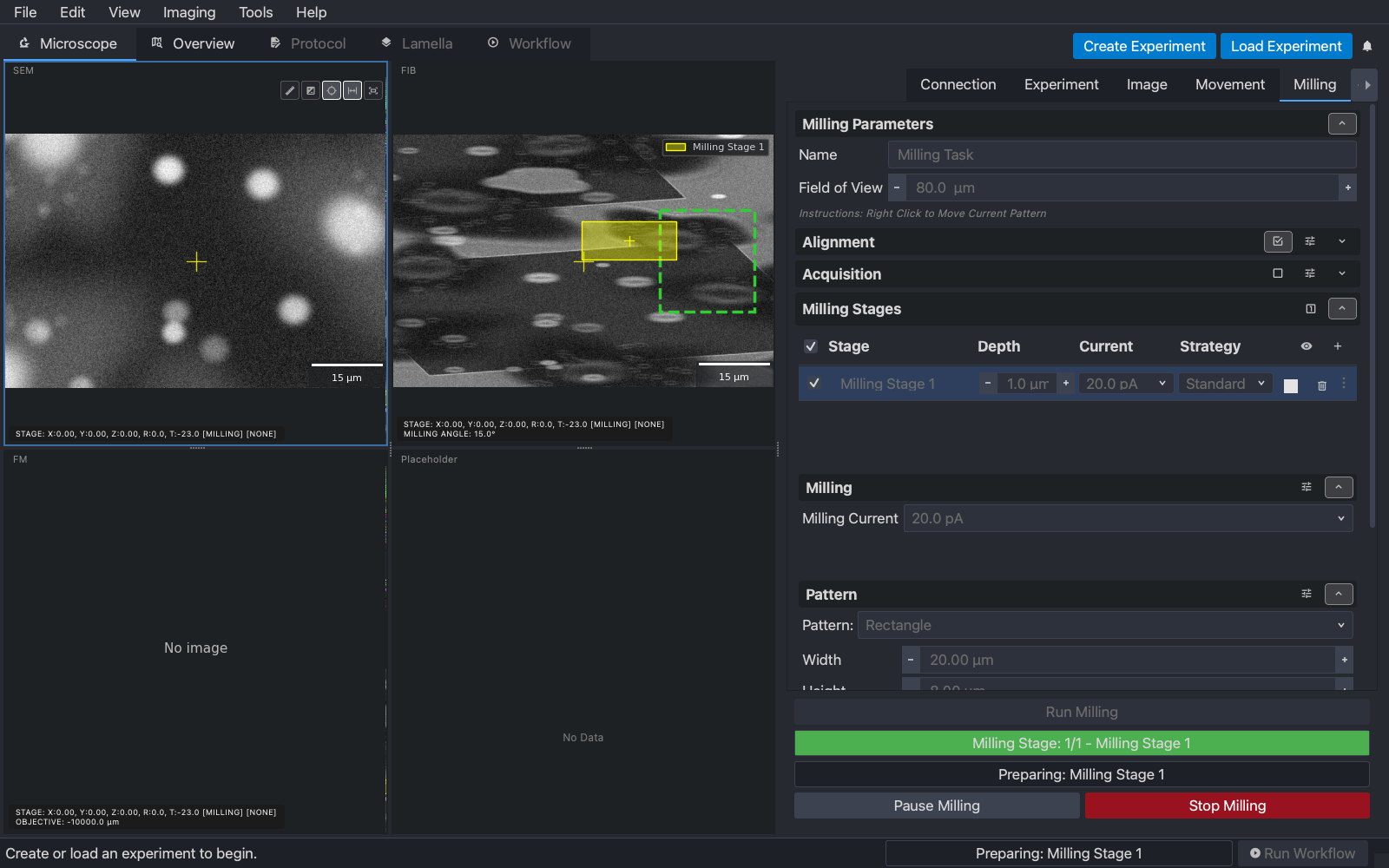
Pause holds the beam and resumes where it left off. Stop ends the task: the current pattern stops where it is, and no further stage runs. On the simulator each pattern takes a few seconds; on an instrument the time depends on the volume and the current, and the workflow shows an estimate.
When the task ends, whether it finished or was stopped, the ion beam is set back to the current and voltage it had before milling started, so the next image is taken at the imaging current and not the milling one.
4. Afterwards
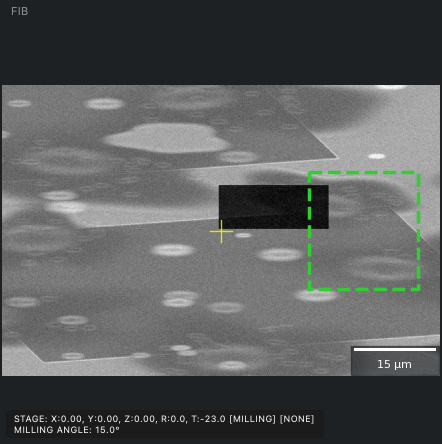
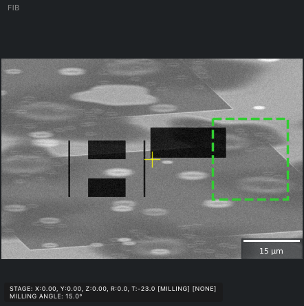
Hide the patterns with the eye button and take fresh images. The rectangle has become a trench, visible in the FIB view where it was milled and in the SEM view from above.
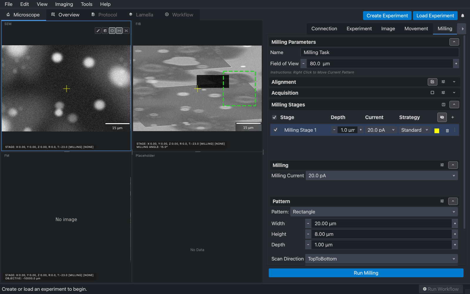
The two-stage task from above, run the same way, leaves what a lamella site looks like after its first pass: the two trenches with the film between them, and the micro-expansion cuts either side.
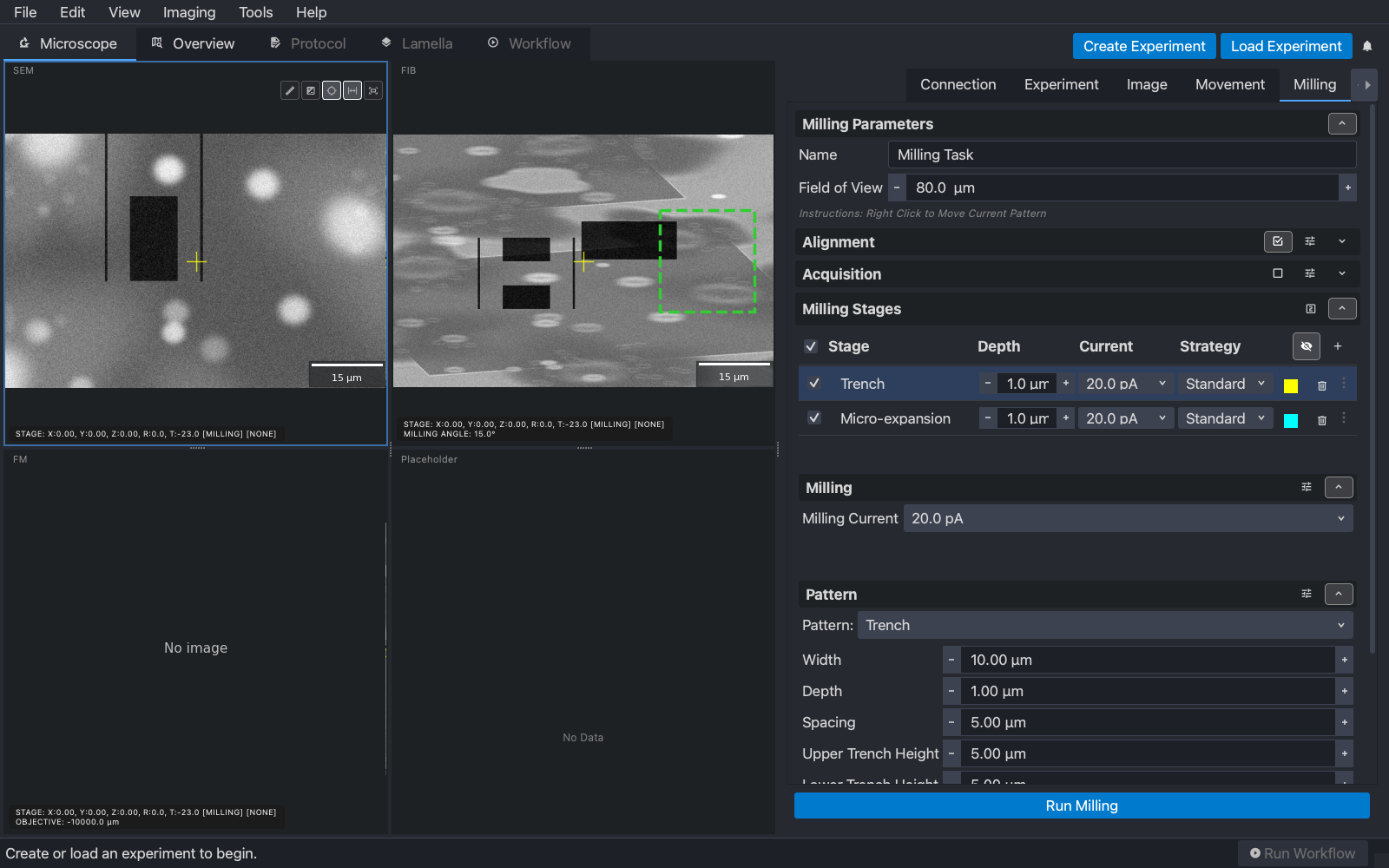
On a real instrument this is where you check the result at a higher magnification before the next stage or the next site. In the AutoLamella workflow, each milling task on this page corresponds to one task in the protocol, with the same stages, patterns and settings, run for you at each lamella.
Next
Sample holder: tell fibsemOS about the shuttle or cassette the grids are in. Or skip ahead to the AutoLamella workflow.